- All
- Articles
- Mini Servicing
- Mini Sport News
- Restoration Projects
- Services at Mini Sport
- Uncategorized
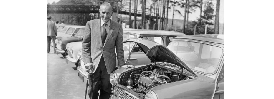
The Original Mini Specialist – Alec Issigonis
As Mini specialists, we owe our profession to those who made this wonderful car brand a worldwide success. So with the 18th November being the birth date of Alec Issigonis, the designer of the original Mini, we’re going to take a look back at his life and career, summing up his contribution to the Mini. [...]
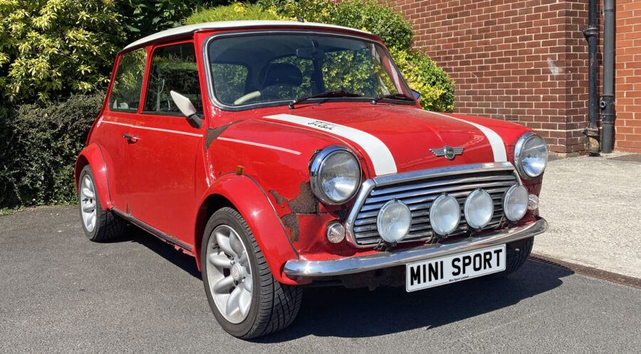
Mini Rust Guide
One word, four letters... Rust. Rust is the arch nemesis of the Classic Mini! With the earliest models right through to the very last Cooper's likely falling victim to this silent torment. No matter the age of your Mini, as even the newest Minis are now in their 20s and the oldest models now in to [...]
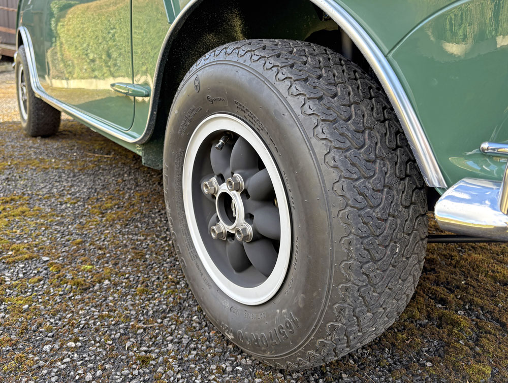
Essential Classic Mini Tyre Checks
Maintaining your classic Mini's tyres is crucial for safety, performance, and comfort. Regular checks can prevent accidents, improve handling, and extend the lifespan of your tyres. Here's a comprehensive guide to tyre maintenance. Maintaining Correct Tyre Pressure Proper tyre pressure is vital for optimal grip, fuel efficiency, and tyre longevity. Under-inflated tyres can lead to [...]

1966 Works Mini JBL 494D Showcased
at BMC Competition Departments 70th Anniversary Display Last weekend saw the 70th anniversary of the BMC Competitions Department - and Mini Sport were delighted to join in the celebrations. A stunning display of ex-works and works supported cars, ranging from the famous red-and-white Mini Coopers to Metro 6R4s were on show at the British Motor Museum at [...]
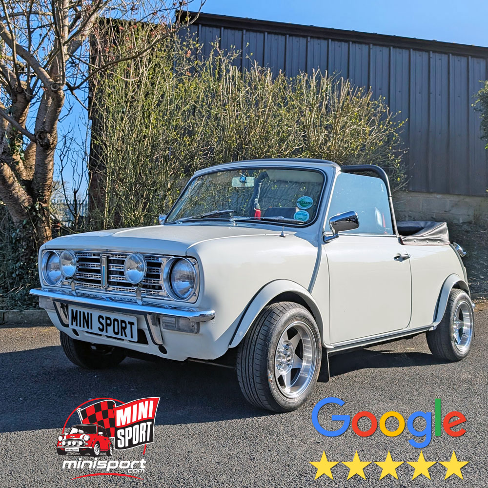
5 Star Review
Suspension Upgrade & Tune-Up Leaves Classic Mini Owners “Thrilled to Bits!” There’s something undeniably special about breathing new life into a Classic Mini — especially when the result puts huge smiles on the faces of the owners. That was the case recently when we welcomed a beautiful White Mini - Clubman Cabriolet into the Mini [...]
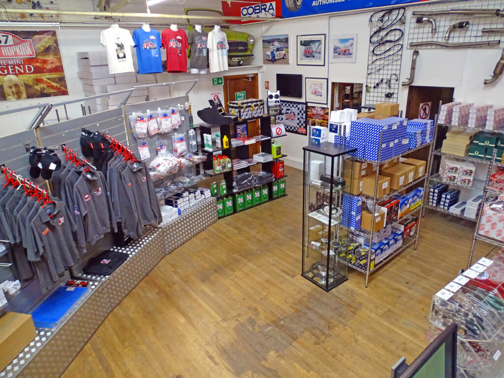
Welcome to Mini Sport
A warm welcome awaits at the Mini Sport Showroom Whether you’re searching for essential Mini parts or looking for expert advice, our friendly and knowledgeable Sales Team is here to help. Come and explore our wide range of high-quality products and enjoy the unique Mini experience that sets us apart. The showroom is open Monday [...]
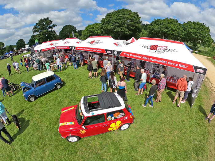
National Mini Day Beaulieu 2025
Join Mini Sport at National Mini Day 2025 – A Must for All Mini Enthusiasts! Sunday 8th June 2025 | 🕙 10:00am – 5:00pm | 📍 Beaulieu, Hampshire SO42 7ZN We’re proud to announce that Mini Sport, sponsors of the Mini Cooper Register, will be attending the National Mini Day 2025 – one of the [...]
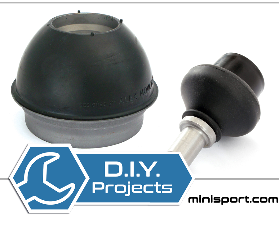
How To: Replace Suspension Cones & Knuckle Joints
This blog will look at the steps to replace your Mini's front & rear suspension cones. Front Suspension Cone Follow instructions for replacing the shock absorber. Remove the front subframe tower bolt (post 76). Use the suspension compression tool through the tower bolt holes to compress the suspension cone. Remove the upper suspension arm to [...]
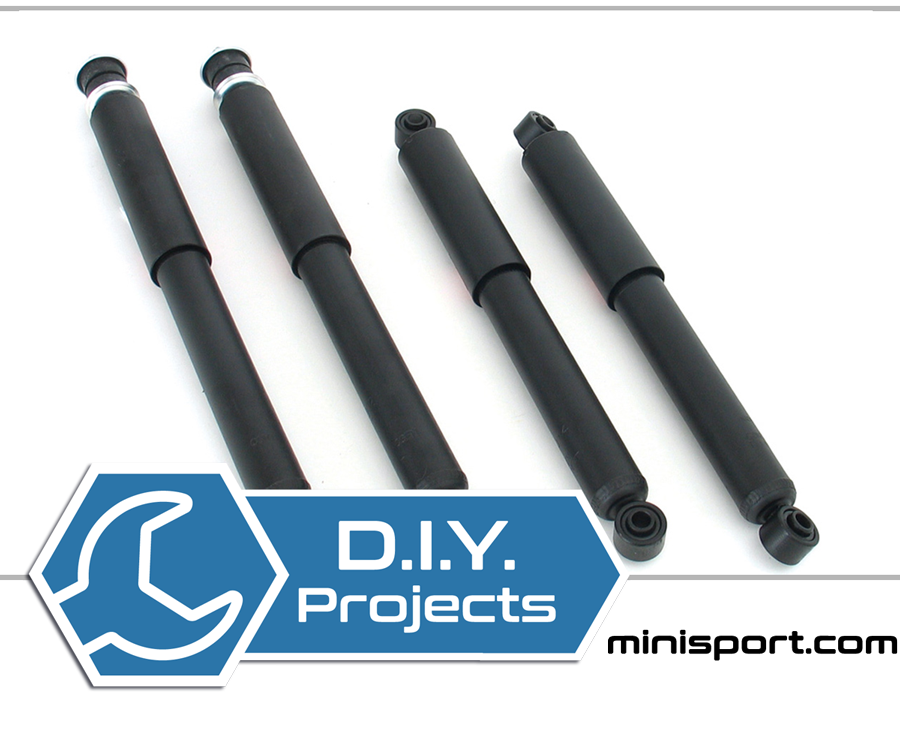
How To: Check / Replace Front & Rear Suspension & Shock Absorbers
A key part of any suspension system, having fully-working shock absorbers will ensure a smooth and safe drive. The pump-like devices keep a vehicle’s tyres in contact with the road by controlling the rebound of its suspension springs – as long as the tyres remain in contact with the road, steering, handling and braking will [...]
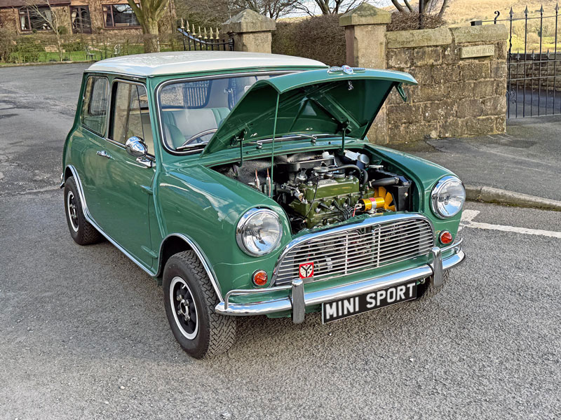
Reviving a Legend
The Mk1 1967 Mini Cooper Restoration Journey Begins At Mini Sport, every classic Mini tells a story – and this Mk1 1967 Mini Cooper 998cc is no exception. Finished in the iconic Almond Green with an Old English White Roof, this little legend is now in our hands for a full ground-up restoration. From its [...]